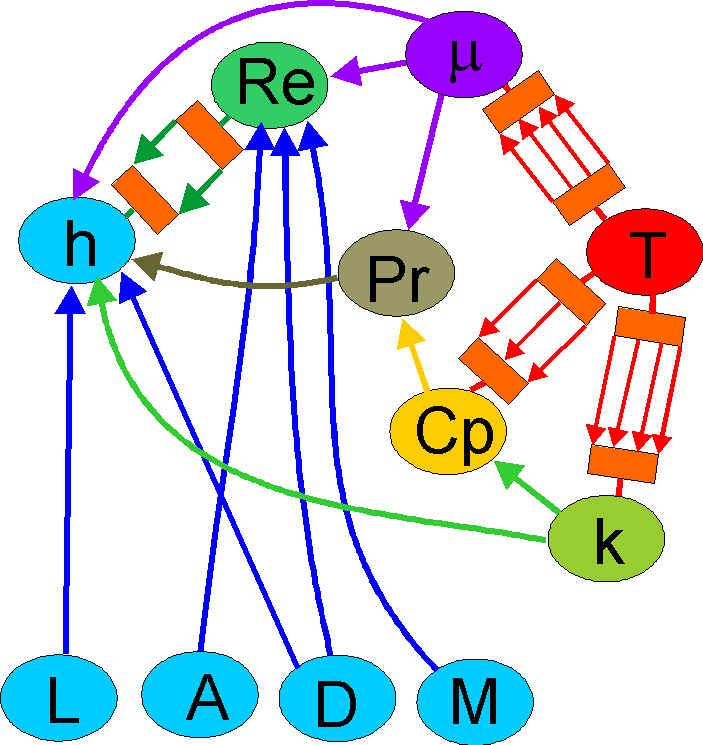
The diagram illustrates a model of the flow in a duct of a jet engine, and its operating regime. State transitions in the regime include laminar to turbulent flow, subsonic through trans-sonic to hypersonic, the viscosity of a fluid changing with temperature, the transition from vapour to gas. As we change the design and its operating point, we want the analytic equations that apply to switch in and out automatically, the switching being controlled at the same level as the rest of the analysis.
A sample set of equations:
| Correlation | Range |
|---|---|
| cp = 1.643989E9 (A0 + A1*T + A2*T2 + A3*T^3 + A4*T^4 + A5*T5 +A6*T^6) | T < 900 |
| cp = 1.643989E9 (B0 + B1*T + B2*T2 + B3*T^3 + B4*T^4 + BA5*T5 +B6*T^6) | 900 <= T <= 1100 |
| cp = 1.643989E9 (C0 + C1*T + C2*T2 + C3*T^3) | T > 1100 |
The value of T can't be known without knowing the Specific Heat Capacity, cp, so IF...THEN... structures would not be of much use in establishing the working point.
The resulting knowledge structure has very much of a wired up machine look about it, the spindling of equations being repeated for each state or regime transition. We can pass ranges of values through this structure, the distributors at the ends handling fragmentation of the ranges, transmission of fragments through the right paths, and the recombination at the other end.
The flow model becomes a small element of the engine model, its undirectedness allowing extension in any direction.