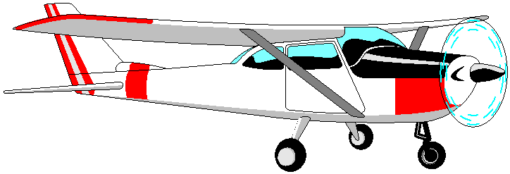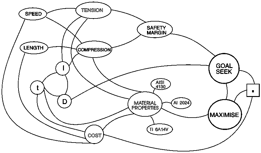
We put this Model together to illustrate various facilities within ORION.

High wing monoplanes like the Cessna typically have a strut connecting a point on the wing to the lower section of the fuselage. The strut is normally loaded in tension, but can be loaded in compression when certain manoeuvres are performed. The strut has a drag force, increasing with speed, which reduces the margin of safety when the strut is in compression.
The Model chooses a suitable material for the strut, based on:
1) Nominated safety margin.
2) Maximum flight speed and G force.
3) The cost of ferrying dead weight.
4) The cost of drag on the plane.
5) Material and machining costs.
6) Typical diameter/thickness ratios for different materials.
The application is typical of a reasonably tight design, where every part of the aircraft is designed to suit a performance envelope - change the performance envelope and every part has to change, including the shape and perhaps the existence of the structure being analysed. Make the plane have a higher top speed and the strut is no longer necessary or desirable, the wings changing shape to suit the different speed. In a larger model, built to encompass more of the design to allow a wider design study of the alternatives, components must "design themselves out" as the performance envelope varies.
A large cross section - lightweight strut pays a drag penalty and is loaded by the drag force. A small, relatively heavy strut is expensive to ferry around. The available materials are aluminium, titanium and steel. The model chooses aluminium at low speed but switches to steel at higher speed. When the switch in material occurs, the shape of the strut changes as well.
The model could be extended in many ways. An increase in maximum design speed might cause the wings to shorten, reducing the length of the strut but increasing the load.
The resultant Model allows variation of parameters to give switching among different materials, and switching out of existence of the strut as the performance envelope changes.
The Model includes:
a) The MAXIMISE Function.
b) Goal seeking to determine a strut diameter given a nominated margin of safety. (Switching is taking place between tensile and buckling failure and for a few other reasons, solving of simultaneous equations is not practicable.)
c) Logical environments in which are specified the properties of the different materials.
 Such a model can be put together in half a day by someone who is
expert in the area. The resulting model can be easily debugged, much faster than for a
program, and can be expanded in any desired direction to encompass more of the design of
the plane. The user of such a model can concentrate on the design problem, trying out
alternatives and "hacking about" until the design is reasonable.
The outline of the knowledge network can only hint at how tangled and intertwined these models can become, because everything depends on everything else, and logical switching among environments can change just the set of simultaneous equations, or the whole nature of the problem - at some point, the strut becomes impractical.
Orion's Knowledge Network Display facility aids the understanding of such models.